Share the idea?

/
Industry Insights
Process
/
Export Limiting for Balcony Solar: The Full Signal Chain from Physics to Firmware
Export Limiting for Balcony Solar: The Full Signal Chain from Physics to Firmware
BituoTechnik
Export limiting (zero feed-in / anti-backflow) is a closed-loop control problem. The energy meter at the grid incomer is the sensor node — and its measurement latency, internal architecture, and communication protocol are among the key variables that influence whether your system behaves reliably in the field. This article walks through the signal chain from the meter’s perspective, and what to look for when selecting a meter for integration.
1. Why Export Limiting Is Harder Than It Looks
On paper, export limiting sounds trivial: measure how much power is flowing back to the grid, tell the inverter to turn down. In practice, it’s a real-time closed-loop control system with latency constraints, measurement accuracy requirements, and regulatory compliance obligations — all of which interact.
1.1 The Physics at the Grid Incomer
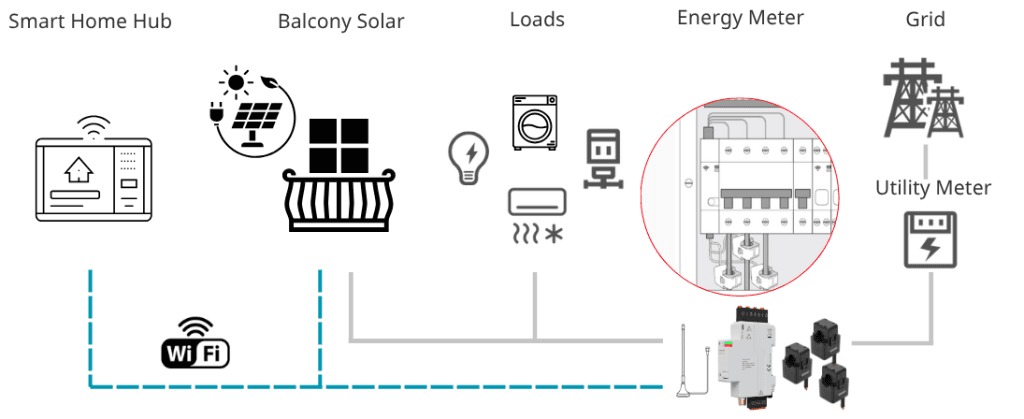
The power balance at the main incomer is:
Pgrid = Pload – PPV
Where:
Pgrid > 0: household is importing from the grid (normal)
Pgrid < 0: household is exporting to the grid (must be limited or zeroed)
Pload: total household consumption — variable, unpredictable
PPV: output from the balcony inverter or storage inverter — variable, and the controllable side of the equation
The control objective is to keep Pgrid ≥ -Plimit, where Plimit is the regulatory export cap (0 W for zero feed-in, or up to 800 W under the 2024 German Balkonkraftwerk regulation).
The meter’s job is to measure Pgrid accurately and deliver that value to the inverter controller fast enough that the control loop can respond before the grid sees a meaningful export event.
1.2 The Latency Budget
Consider a common scenario: a household load suddenly drops by 600 W (an oven turns off). The inverter is producing 400 W. Without export limiting, the system would immediately export 200 W. With export limiting, the control loop must:
Detect the load drop via Pgrid measurement
Communicate the new Pgrid to the inverter MCU
Calculate the required output reduction
Adjust the inverter output
A typical system targets 2–5 seconds end-to-end response, though the actual budget depends heavily on the inverter design and local grid code requirements. Here’s how the meter-side contribution breaks down:
Stage | Typical Budget | Notes |
|---|---|---|
Metering IC → valid power reading | ≤ 200 ms (SDM01G2X & Combo Gen2) | RMS calculation window; the measurement floor |
MCU reads IC + Wi-Fi SoC transmits | + 50–100 ms | Internal UART + UDP packetization |
Network transit (LAN) | + 10–30 ms | Local Wi-Fi; negligible |
Inverter MCU receives + runs algorithm | + 50–100 ms | Depends on inverter MCU design |
Inverter output adjustment | varies | Determined by inverter design and applicable grid code — typically the dominant variable in the overall response time |
The meter’s contribution to total latency is typically under 300 ms. From the meter side, what matters most is consistency (low jitter) and reliable behavior when connectivity is lost — not raw update speed.
One note for three-phase households: even if the balcony inverter is single-phase (typically connected to L1), export limiting is generally measured at the total three-phase incomer — not just L1. Load on L2/L3 provides headroom that allows L1 to export without the total Pgrid going negative. How this is handled is a system design decision for the inverter manufacturer, but it’s worth factoring into meter selection.
2. Why Standard Wi-Fi Meters Struggle with Export Limiting
A common assumption is that any off-the-shelf Wi-Fi energy meter is interchangeable for this application. However, standard meters are primarily designed for low-frequency monitoring and logging, whereas export limiting requires a real-time sensor node.
The unreliability of standard meters in export limiting applications usually stems from several underlying hardware and firmware bottlenecks:
Poor Low-Current Accuracy: The control target for zero feed-in is typically around 0 W, meaning the meter frequently operates at extremely low currents. Current Transformers (CTs) and electronic systems used in consumer meters might suffer from degraded linearity and amplified phase angle errors at low loads. This feeds incorrect data to the inverter, causing the control loop to oscillate.
Suboptimal Firmware Scheduling: Most off-the-shelf meters are not designed for real-time operation. Their firmware often prioritizes Wi-Fi connectivity or cloud reporting, which can interrupt or delay the underlying metrology sampling processes. Without deep optimization of the metering IC’s RMS calculation window, outputting stable, high-frequency power data is nearly impossible.
Single-MCU Resource Contention: Many consumer-grade meters use a single microcontroller (e.g., an ESP32) to handle both energy measurement and Wi-Fi communication. When the network fluctuates, the device reconnects, or complex protocols are processed, CPU resources are preempted. In a real-time control system, this resulting “data blackout” is fatal.
The Dual-Chip Solution: Built for Real-Time Control
To address these pain points, the Bituo SDM01 Gen2 Combo and SDM01 G2X feature a system-level redesign. Beyond utilizing high-precision CTs and purpose-built metering ICs, they employ a Dual-Chip Architecture — a dedicated metering MCU communicates with a separate Wi-Fi SoC (ESP32-C6) via UART.
The measurement and communication layers are computationally and electrically isolated. For export limiting applications, this separation offers three practical advantages:
1. Measurement continuity under Wi-Fi stress: The metering IC continues producing readings at its full update rate regardless of Wi-Fi stack activity. The ESP32-C6 handles connectivity independently — reconnection events, OTA updates, and protocol processing do not affect the measurement layer.
2. More deterministic update rate: The metering IC’s RMS calculation runs on its own clock, deeply co-optimized with the metering MCU. The ≤ 200 ms update rate is a hardware characteristic of the metering subsystem — not a software scheduling target that can be preempted by Wi-Fi activity.
3. Firmware independence for ODM development: Because the ESP32-C6 communication layer is physically separate from the metering MCU, ODM partners can develop and flash custom firmware on the ESP32-C6 — implementing proprietary protocols, custom encryption, or direct cloud integration — without modifying the metrology firmware. Teams that want to own their communication stack can do so while relying on the meter’s certified measurement accuracy.
(Note: The SDM01 G2X also offers an external SMA antenna connector — useful for inverter and storage enclosures where metal panels attenuate Wi-Fi signals for any meter with a built-in PCB antenna.)
3. Communication Protocol Selection
The meter communicates Pgrid to the inverter MCU over local Wi-Fi/LAN. Protocol selection affects latency, implementation complexity, and security compliance.
3.1 Raw UDP Push — The Primary Channel
Why UDP, not TCP?
TCP’s connection management overhead (SYN/ACK, retransmission, congestion control) adds variable latency. For export limiting, data freshness generally matters more than delivery guarantee — if a UDP packet is lost, the next one arrives within the configured push interval. Whether this trade-off is acceptable depends on the inverter’s control loop design, but it is the basis for why UDP push is the primary channel in our implementation.
How it works:
The meter pushes a UDP packet to the inverter MCU’s IP:Port at the configured interval
No persistent connection required; the meter pushes autonomously after provisioning
Payload contains Pgrid (W), timestamp, and device ID
Push interval: 200–500 ms configurable; 200 ms is the setting most commonly used for export limiting
On the inverter side, a timeout-based fail-safe trigger is the standard approach: if no packet is received within a defined window, the inverter falls back to a safe output state. A common reference point is to set the timeout at a multiple of the configured push interval — long enough to tolerate occasional packet loss, short enough to respond to a genuine connectivity loss. The right value depends on your control loop design and certification requirements.
3.2 Modbus TCP — The Fallback Channel
If your inverter or storage MCU already has a Modbus stack (common in systems that also support RS-485 Modbus RTU), Modbus TCP polling is a viable alternative.
Key constraints to be aware of:
Single connection model: Open → read register → close per cycle. Holding a persistent connection is not recommended; the meter’s TCP stack has limited concurrent connection capacity.
Polling interval: A conservative polling interval — on the order of several seconds — is advisable. Polling too aggressively can overwhelm the ESP32-C6’s TCP stack and cause connection instability. For real-time export limiting, this makes Modbus TCP a fallback rather than a primary channel.
Latency: Higher than UDP due to TCP handshake overhead on each cycle.
3.3 UDP AES — For Security-Compliant Deployments
The EU Radio Equipment Directive (RED) and EN 18031 cybersecurity standards increasingly require encrypted data transmission for Wi-Fi-connected IoT devices. UDP AES provides the same push architecture as Raw UDP, with AES-128 encryption applied to each packet. The pre-shared key is shared with the BLE broadcast key, enabling unified key provisioning at commissioning. Encryption overhead on the meter side is minimal.
3.4 Device Discovery
In residential installations, the meter’s IP may change after a router reboot. Two common approaches:
mDNS: meter broadcasts
sdm01-xxxxxx.local; inverter MCU resolves at startup and re-resolves on failure. No manual configuration required.DHCP-reserved static IP: router assigns a fixed IP by MAC address. More reliable where mDNS is filtered by enterprise or operator-grade routers.
4. Control Algorithm — A Reference Perspective
The control algorithm lives in the inverter or storage MCU — that’s the inverter manufacturer’s domain, and the right design depends on the specific inverter architecture, grid code requirements, and certification obligations. What we can offer here is a reference framing from the meter side.
4.1 A Common Reference Approach: PI Control with Ramp Rate Limiting
Among the implementations we’re aware of in the field, a PI controller with ramp rate limiting is a common pattern:
e(t) = Pgrid(t) – Plimit
Psetpoint(t) = Kp · e(t) + Ki · Σ e(k) · Δt
With ramp rate constraint:
ΔPsetpoint = clamp( Psetpoint(t) – Psetpoint(t-1), -Rdown, Rup )
Where Rdown and Rup are the ramp-down and ramp-up rates, typically set in accordance with local grid codes.
The specific gain values and ramp rates need to be tuned for each inverter system. From the meter side, what this means practically is that consistent, low-jitter data delivery matters more than raw update speed: a control loop tuned around a 200 ms data source will behave differently if the actual delivery interval varies unpredictably.
4.2 Fail-Safe Behavior — The Inverter Manufacturer’s Decision
If the meter goes offline, the inverter needs a defined response. What that response should be is a system design and regulatory compliance decision for the inverter manufacturer — grid codes may have specific requirements.
From the meter side: the SDM01 provides a clean, detectable signal loss (UDP packets simply stop arriving) that makes a timeout-based fail-safe straightforward to implement. After a Wi-Fi dropout, the meter resumes pushing within its configured interval once connectivity is restored — the reconnection behavior is deterministic.
One consideration worth building into the recovery logic: validating a short sequence of consecutive readings before resuming normal control, rather than acting immediately on the first packet after reconnection. This guards against acting on a stale or buffered reading. The specific implementation is an inverter-side design decision.
The fail-safe output level, recovery ramp rate, and validation logic are all inverter-side design decisions that should be validated against the applicable grid code and certification requirements.
5. Validation: A Few Meter-Specific Considerations
Your team will have your own test cases and certification requirements. A few areas specific to the meter integration that are worth including in your test plan if not already there:
Fail-safe trigger and recovery: Does the inverter respond correctly when the meter goes offline? Does it recover cleanly after reconnection, without acting on stale data?
Network stress behavior: How does the control loop behave under packet loss or latency spikes? Does mDNS re-discovery work reliably after a DHCP reassignment?
Three-phase summation: If your target market includes three-phase households, verify that total Pgrid correctly sums all three phases under phase-imbalanced load conditions.
6. Selecting a Meter Partner: What We Hear From Integration Teams
If you’re evaluating meter partners for ODM or integration, here’s what tends to come up in conversations with inverter and storage product teams:
Metrology accuracy and certification. Measurement error directly affects system behavior — over-limiting reduces yield, under-limiting risks grid export violations. IEC 61557-12 Class 1 test record tracked for every product delivered is the baseline most teams ask for.
Communication latency and consistency. The numbers that tend to matter most: ≤ 200 ms measurement update rate, low UDP push jitter, and reliable reconnection after Wi-Fi dropout. Consistency is often more important than peak speed.
Firmware openness and long-term supply. For ODM partnerships, the ability to run custom firmware on the communication SoC — without affecting metrology — is frequently a deciding factor. Long-term hardware availability (5+ years) is also a real concern for consumer electronics programs.
Electrical reliability and safety design. CE/RED compliance is a baseline, not a differentiator. What actually matters is the underlying electrical design – such as adequate creepage and clearance distances, verified operation across the full temperature and humidity range, and a track record of long-term field stability. Ask for the design rationale, not just the DoC.
Integration support quality. Complete documentation with code examples, a dedicated engineering contact, and reasonable response times on technical questions. This is often what separates a smooth integration from a frustrating one.
7. How Bituo Technik Fits Into Your System
The SDM01 Gen2 Combo and SDM01 G2X are designed with the integration scenarios above in mind:
Consideration | SDM01 Gen2 / G2X |
|---|---|
Measurement update rate | ≤ 200 ms (dedicated metering IC + MCU, hardware guarantee) |
Primary communication | Raw UDP push, configurable 200–500 ms interval |
Fallback communication | Modbus TCP |
Security | UDP AES-128, EN 18031 / RED compliant |
Device discovery | mDNS + DHCP static IP |
Accuracy | IEC 61557-12 Class 1 |
Wi-Fi SoC | ESP32-C6 (open UART interface for custom firmware) |
Antenna | Built-in PCB (Combo) / External SMA (G2X — for metal enclosures) |
OTA firmware update | Supported |
ODM / custom firmware | Available — contact us |
For ODM partners, we offer custom firmware builds on the ESP32-C6 with your proprietary communication protocol, white-label hardware, NDA-protected integration support, and long-term supply commitment on the SDM01 platform.
→ Full SDM01 G2X & Combo Gen2 Integration Guide
→ Contact Bituo Technik for ODM / Integration Partnership