Share the idea?

/
Industry Insights
Process
/
Introduction to Dynamic Load Balancing (DLB) over Wi-Fi for Home EV Charging
Introduction to Dynamic Load Balancing (DLB) over Wi-Fi for Home EV Charging
As electric vehicle (EV) adoption accelerates, the electrical grids in our homes are facing increasing stress. For EV charger manufacturers, Dynamic Load Balancing (DLB)—also known as active load management or anti-tripping—is becoming an essential feature rather than just a premium add-on.
While traditional DLB relies on hardwired RS485 connections—which remains a highly reliable standard for large commercial and fleet deployments—we are seeing a growing trend towards Local Area Network (Wi-Fi/LAN) integration for residential applications. For home EV charging, Wi-Fi DLB can help reduce installation costs, minimize the need for long cable runs through finished walls, and simplify the user experience. However, it also introduces specific challenges for firmware engineers regarding network reliability, protocol selection, and fail-safe design.
In this introductory guide, we will share some insights into the architecture of Wi-Fi-based DLB for residential use, compare common communication protocols, explore basic closed-loop control strategies, and look at typical setups for multi-EV households.
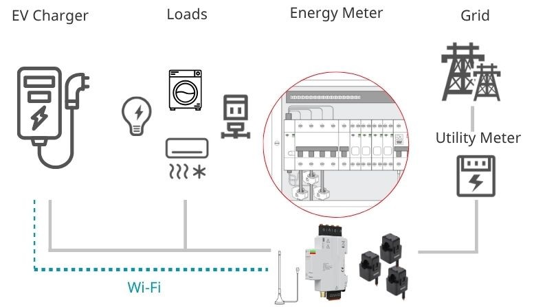
Typical Wi-Fi DLB System Architecture
1. The Core Mathematics of DLB
At its core, DLB operates as a closed-loop control system. The smart meter continuously monitors the total grid import current (Igrid) at the main incomer. The EV charger’s Main Control Unit (MCU) uses this data to dynamically adjust its PWM duty cycle, helping to ensure the total household load stays within the main circuit breaker rating (Imax).
A common approach to calculate the available current for the EV uses a straightforward formula:
Iavailable = Imax – Isafe – (Igrid – Iev)
Imax: Main circuit breaker rating (e.g., 60 A).
Isafe: Safety headroom, typically 10–20% of Imax (e.g., 6 A).
Igrid: Real-time total grid import current read from the meter.
Iev: The current output of the EV charger.
(Note: The term (Igrid – Iev) represents the baseline load of all other household appliances.)
For 3-phase systems, a widely adopted strategy is to use the worst-phase current (Igrid = max(IL1, IL2, IL3)) to help protect the most heavily loaded single-phase breaker from tripping.
2. Choosing the Right Communication Protocol
When moving from RS485 to Wi-Fi, firmware engineers often evaluate how the meter and the charger should communicate. Different deployment scenarios typically call for different protocols.
Protocol | Direction | Typical Interval | Best For | Notes |
|---|---|---|---|---|
Raw UDP | Meter → Charger (Push) | 0.5–1 s | High-frequency DLB | Low latency; AES encryption available |
HTTP polling | Charger → Meter (Pull) | 3–5 s | Mid/low-frequency DLB | Simple; same JSON as UDP |
Modbus TCP | Charger → Meter (Poll) | 3–5 s | Existing Modbus stacks | ⚠️ Typically single client only |
MQTT | Meter → Broker (Push) | 1–5 s | Multi-charger / HEMS | Requires broker host |
WebSocket | Bidirectional | Continuous | Persistent real-time | WSS for encrypted variant |
High-Frequency Delivery: Raw UDP (Push)
For high-frequency DLB (e.g., 0.5–1s intervals), UDP is generally considered highly efficient. Instead of the charger polling the meter, the meter pushes a JSON payload to the charger’s IP address.
Key Advantages: Minimal connection overhead and no TCP handshake latency. It allows the charger’s MCU to spend more clock cycles managing the charging session rather than managing network sockets.
Security: Can be paired with AES encryption (UDP AES) to help secure the payload while maintaining low latency.
Mid-Frequency Polling: HTTP & Modbus TCP
For systems where 3–5s polling intervals are sufficient, polling protocols are a practical choice.
HTTP Polling: A simple and widely supported method. The charger pulls data via a standard GET request, receiving the same JSON payload structure as UDP. It is generally reliable for mid-to-low frequency updates.
Modbus TCP: If your charger platform already has a robust Modbus TCP stack, this is a viable option. Consideration: Embedded Wi-Fi meters often support only one concurrent TCP connection. If a secondary device (like a home automation system) tries to poll the meter simultaneously, it may disrupt the charger’s DLB data acquisition.
⚠️ A Note on HTTPS: It is generally not recommended to use HTTPS for high-frequency polling (< 3s). Every HTTPS request triggers a full TLS handshake. On typical embedded Wi-Fi SoCs, this can saturate the CPU and cause watchdog resets. HTTPS is better suited for low-frequency configuration writes.
3. Closed-Loop Control Logic & Fail-Safe Design
A robust DLB algorithm typically balances safety (preventing breaker trips) with stability (preventing the EV’s Battery Management System from terminating the session due to erratic current changes).
Common Asymmetric Ramp Strategies
Ramp-Down (Fast): If Igrid > Imax – Isafe, the charger usually reduces the PWM duty cycle immediately. This action is safety-critical and is often designed to complete within < 2 seconds.
Ramp-Up (Slow): When household load drops and surplus current is available, the charger typically ramps up gradually (e.g., +1A steps every few seconds) to help prevent control oscillation.
Fail-Safe Mechanisms
What happens if the home Wi-Fi router crashes or the connection drops? A reliable DLB system should ideally handle communication losses gracefully to prevent overloading the home circuit.
A typical fallback mechanism might include:
Timeout Trigger: No data received from the meter for a set period (e.g., 10 consecutive seconds).
Action: Automatically force the charging current to the minimum safe value (6 A, per IEC 61851-1) or suspend charging entirely.
Recovery: Automatically exit the fallback state only after a stable connection is re-established (e.g., 3 consecutive successful data packets).
4. Multi-Charger Architectures (Multi- EV Households & Light Commercial)
While RS485 is often the standard for large commercial parking lots, Wi-Fi DLB can be a practical alternative for multi-EV households (e.g., two chargers sharing a single home electrical panel) or light commercial sites.
Architecture A: Centralized Arbiter (Local)
One entity (a designated “Master” charger or a local HEMS gateway) receives the Igrid data from the meter via UDP or MQTT. The Arbiter calculates the available capacity and distributes individual current limits to “Follower” chargers over the home LAN. This approach is generally reliable and works offline.Architecture B: OCPP Cloud Coordination
The meter pushes data to a Cloud CSMS (Charging Station Management System) via MQTT/HTTP. The cloud then issues individual power schedules to all chargers via OCPP (SetChargingProfile). This is more common in light commercial setups but relies on internet uptime.
5. A Note on Hardware: Evaluating Wi-Fi Energy Meters for DLB
Based on our experience as a meter manufacturer, when evaluating hardware for residential DLB, EV charger developers often look for a few key capabilities:
High-Speed RMS Measurement: The meter should ideally capture accurate RMS current and power values rapidly. Responsive DLB often benefits from data refresh rates of ≤ 0.5 seconds. For more demanding applications, such as Solar Export Limiting, response times down to 0.2 seconds are sometimes required.
Comprehensive Open LAN APIs: It is often beneficial to have native support for local protocols including mDNS (helpful for robust IP discovery), UDP Push, HTTP, Modbus TCP, and MQTT. Additionally, offering encryption options (e.g., UDP AES, MQTTS) helps meet modern cybersecurity standards like EN 18031.
Reliable RF/Wi-Fi Performance: Electrical consumer units are often metallic and can block RF signals. A well-optimized antenna and RF design helps maintain a stable connection, reducing the need for homeowners to install Wi-Fi extenders or complex mesh networks.
Custom Firmware Capabilities (For B2B Clients): For enterprise clients with proprietary ecosystems, having the option to flash custom firmware onto the Wi-Fi SoC can be a major advantage. Crucially, the hardware architecture should ensure that running custom communication firmware does not affect the core metrology accuracy or calibration data.
As a meter manufacturer, we designed the SDM01 G2X and SDM01 Combo Gen2 with these specific use cases in mind. Built on the ESP32-C6, they are engineered to provide 0.5s UDP pushes, robust local APIs, solid RF penetration, and a dual-MCU architecture that safely isolates metrology from custom Wi-Fi firmware.
Summary
Wi-Fi DLB offers a practical approach for residential applications where ease of installation is a priority. From our perspective, a successful implementation usually comes down to a few key design choices:
Protocol: Utilizing UDP push for ≤ 1 s intervals, or HTTP for 3–5 s intervals; being mindful of Modbus TCP limitations in multi-client scenarios.
Control loop: Implementing an asymmetric ramp (fast down, slow up).
Fail-safe: Designing and testing clear fallback behaviors for network drops.
Multi-charger: Choosing a clear coordination architecture, such as a Centralized Arbiter (local) or OCPP (cloud).
Addressing these four areas can help build a residential DLB system that effectively protects against tripping, degrades gracefully under fault conditions, and delivers a smoother experience for the end user.