Share the idea?

What Is A RDC-DD, RDC-MD And RDC-PD?
Liu Hualei | Bituo Technik
Editor's Note (Sept 2026 Update): We've updated this fundamental guide to reflect the latest market shifts since the IEC 62955:2018 standard—specifically the industry's transition toward highly integrated modules and the compliance challenges of built-in designs.
💡 For EV Charger R&D Engineers & Product Managers: If you are evaluating protection technologies for your new wallbox design, check out our in-depth guide.
What is an RDC-DD (Residual Direct Current Detecting Device)?
RDC-DD is the abbreviation of Residual Direct Current Detecting Device, to be used for Mode-3 charging of electric vehicles.
It is the IEC 62955:2018 standard that specifies RDC-DD to ensure that the proper functionality of RCDs Type A or Type F is not impaired by DC residual currents above 6 mA. RDC-DDs are intended to disconnect the power supply to the EV in cases where a smooth residual direct current equal to or above 6 mA is detected.
According to IEC 62955:2018, RDC-DDs are classified into the following two main classes:
RDC-MD (Residual Direct Current – Monitoring Device): Primarily used for monitoring DC residual currents to prevent Type A or Type F RCDs from malfunctioning due to DC leakage above 6 mA.
RDC-PD (Residual Direct Current – Protection Device): Provides both monitoring and protection against AC residual currents and pulsating DC residual currents, in addition to protecting against DC residual currents above 6 mA.
RDC-MD vs. RDC-PD: Understanding the Core Differences
The major difference between RDC-MD and RDC-PD is whether protection against AC 30 mA and pulsating DC residual current is integrated into the device.
In other words, an RDC-MD cannot protect humans from being injured or electrocuted by AC 30 mA and pulsating DC residual current. However, it can monitor DC residual currents to avoid RCDs Type A or Type F being impaired by DC residual currents above 6 mA. Therefore, RDC-MD is also commonly referred to as a DC RCM (Residual Current Monitor) by some engineers.
For RDC-MD, IEC 62955:2018 further classifies its type of construction as follows:
RDC-MD with mechanical switching in one unit
RDC-MD consisting of RDC-M-unit mechanically coupled to a separate protective device
RDC-MD consisting of an RDC-M-module electrically coupled to a separate protective or switching device
Common RDC-DD Designs in Real-World EV Chargers
The EV charging infrastructure market is fiercely competitive, driving manufacturers to constantly seek the most cost-effective yet compliant RDC-DD designs. Since the publication of IEC 62955 in 2018, the Bituo Technik team has supported hundreds of EV charger manufacturers in their RDC-DD integration.
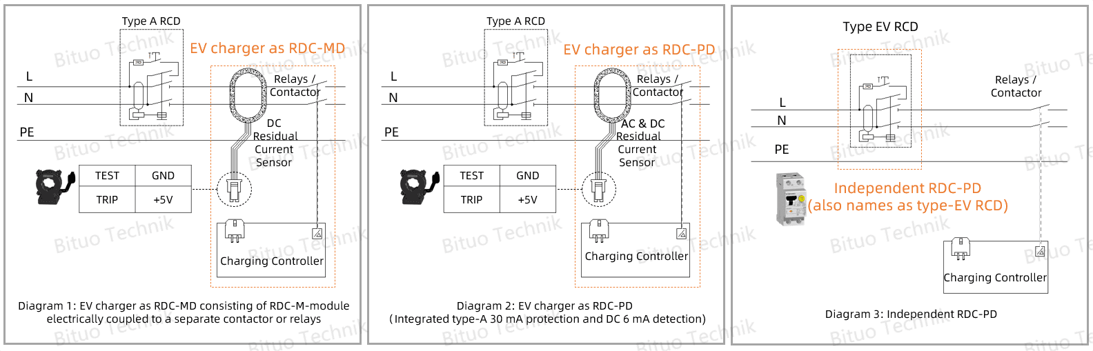
Based on our extensive field experience, the following three design architectures have emerged as the industry mainstream:
EV charger as RDC-MD: Consisting of an RDC-M-module electrically coupled to a separate contactor or relays (See Diagram 1).
EV charger as RDC-PD: Integrating both Type-A 30 mA protection and DC 6 mA detection within the charger's internal system (See Diagram 2).
Independent RDC-PD: Also known as a Type-EV RCD, functioning as a standalone protective device (See Diagram 3).
Expert Engineering Insight: Why External Type-A RCCBs are Still Recommended
💡 While Diagram 2 shows an EV charger acting as an RDC-PD, the author strongly recommends installing a traditional Type-A 30 mA RCCB or RCBO upstream (outside the EV charger).
Why? An EV charger might technically provide Type-A 30 mA protection through a coordinated system consisting of a charging controller, an AC/DC residual current sensor, and switching devices. However, the long-term reliability of this multi-component coordination is still highly debated in the industry. Compared to traditional, all-in-one Type-A RCCBs/RCBOs, an external, dedicated protective device offers a much more robust and fail-safe layer of electrical protection.
The Declining Market Share of Standalone RDC-PDs
It is worth noting that since the standard's release, the market share of independent, standalone RDC-PDs has noticeably declined. Driven by strict cost controls, compact wallbox designs (space constraints), mature market education, and the need for smarter energy management, EV charger manufacturers are increasingly favoring highly integrated, cost-effective solutions like RDC-M-modules and Built-in Type-A mRCDs (IEC 60947-2).
For EV charger manufacturers, integrating AC & DC or dedicated DC residual current monitoring directly into the PCBA is far more cost-effective than purchasing bulky standalone units, perfectly satisfying safety compliance without redundant hardware.
However, this trend hides a potential risk: How reliable are these low-cost AC EV chargers that claim to integrate Type-A 30mA protection for human safety?
Fortunately, electricians in many countries have developed a best-practice habit of installing an external Type-A RCCB or RCBO upstream, regardless of what the EV charger manufacturer claims. Take China as an example: for EV chargers installed in private parking spaces, an external Type-A voltage-dependent RCBO is often equipped in the power distribution box next to the EV charger.
Design Advice: Shall I Claim Built-in RDC-PD or RDC-MD?
An RDC-PD is a protective device that combines AC, pulsating DC, and 6mA DC detection with evaluation and mechanical switching, all within a single unit. It is suitable for isolation and must comply with the strict requirements of IEC 61008 or IEC 61009, as outlined in Annex O (normative) of IEC 62955:2018.
However, due to limitations in components such as power relays or contactors acting as the mechanical switching elements, achieving full compliance with IEC 61008-1 or IEC 61009-1 for a built-in RDC-PD is highly challenging.
Therefore, a more accurate and compliant approach for R&D engineers is to ask: Should I design a built-in Type-A mRCD & RDC-MD combination, or should I opt for a built-in RDC-MD design and include guidance in the installation manual for electricians to ensure the use of an external Type-A RCCB/RCBO?
We recommend making this decision based on your target market and the region where the charger will be used:
Built-in Type-A mRCD (IEC 60947-2) & RDC-MD (IEC 62955): Suitable for markets like the UK, Nordic countries, and China.
Built-in RDC-MD (IEC 62955): More commonly used in European continental countries - such as Germany, and France - where voltage-independent Type-A RCCB/RCBO are compulsory to be installed
If your EV charger is to be sold across multiple regions, we suggest implementing both built-in designs on a single charging control board. For instance, by selecting Bituo Technik’s BRCS Series residual current sensors, which feature two independent fault alarm output pins (one for Type-A 30mA & DC 6mA, and another for dedicated DC 6mA detection), you can easily achieve a dual built-in design on a single control board.
Summary: Holding the Bottom Line on Electrical Safety in EV Charger Design
While standalone RDC-PDs and integrated RDC-M-modules have coexisted since the introduction of IEC 62955, the market's overwhelming shift toward highly integrated modules reflects the EV charging industry's relentless pursuit of cost-efficiency and compact design.
However, as we have explored, integrating these functions directly into the EV charger introduces complex compliance challenges, particularly regarding the strict mechanical switching requirements of IEC 61008 and IEC 61009.
To ensure charging safety, the most prudent approach is to align your protection strategy with your target market's specific regulations and installation habits. Whether you implement a built-in RDC-MD that relies on an external voltage-independent Type-A RCD, or a dual-protection architecture (Built-in Type-A mRCD & RDC-MD), the priority must always be robust, fail-safe electrical safety.
By understanding the nuanced differences between RDC-MD and RDC-PD, and acknowledging the physical limitations of internal relays and contactors, R&D engineers can navigate the complexities of IEC 62955 to deliver wallboxes that are both economically competitive and uncompromisingly safe.